| 1. |
Which one of the following is required when field screening the individual buildings. |
|
|
Verifying and updating building identification information, |
|
|
Walking around the building and sketching a plan and elevation view on the Data Collection Form. |
|
|
Determining occupancy (that is, the building use and number of occupants). |
|
|
Determining soil type, if not identified during the pre-planning process. |
|
|
Identifying potential nonstructural falling hazards. |
|
|
Identifying the seismic-lateral-load-resisting system (entering the building, if possible, to facilitate this process) and circling the Basic Structural Hazard Score on the Data Collection Form. |
|
|
Identifying and circling the appropriate seismic performance attribute Score Modifiers (e.g., number of stories, design date, and soil type) on the Data Collection Form |
|
|
Determining the Final Score, S (by adjusting the Basic Structural Hazard Score with the Score Modifiers identified in Step 7), and deciding if a detailed evaluation is required. |
|
|
Photographing the building. |
|
|
All of the above. |
| 2. |
In Table 3-1, S1 is an example of a moment free building. The 1994 Northridge and 1995 Kobe earthquakes showed that the welds in steel moment- frame buildings were vulnerable to severe damage. The damage took the form of broken connections between the beams and columns.

|
|
|
True |
|
|
False |
| 3. |
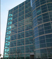
In table 3-1, S2 is an example of a braced steel frame. These buildings are braced with diagonal members, which usually can not be detected from the building exterior. In recent earthquakes, braced frames were found to have damage to brace connections, especially at the lower levels.
  |
|
|
True |
|
|
False |
| 4. |
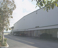
In table 3-1, S3 is an example of a light metal building. In these buildings insufficient capacity of tension braces can lead to their elongation and consequent building damage during earthquakes. Inadequate connection to a slab foundation can allow the building columns to slide on the slab. Loss of the cladding can occur.
 |
|
|
True |
|
|
False |
| 5. |
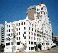
In table 3-1, S4 is an example of Steel frames with cast-in place concrete shear walls. An interior investigation will permit a wall thickness check. More than six inches in thickness usually indicates a concrete wall. Shear cracking and distress can occur around openings in concrete shear walls during earthquakes. Wall construction joints can be weak planes, resulting in wall shear failure below expected capacity.
 |
|
|
True |
|
|
False |
| 6. |
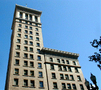
In table 3-1, S5 is an example of Steel frames with un-reinforced masonry infill walls. In these structures, Steel columns are relatively thin and may be hidden in walls. Usually masonry is exposed on exterior with narrow piers (less than 4 ft wide) between windows.
- Portions of solid walls will align vertically.
- Infill walls are usually two to three inches thick. Veneer masonry around columns or beams is usually poorly anchored and detaches easily.
 |
|
|
True |
|
|
False |
| 7. |
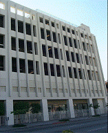
The building bellow is an example of Concrete moment resisting frames. In this building; Large spacing of ties in columns can lead to a lack of concrete confinement and shear failure, Lack of continuous beam reinforcement can result in hinge formation during load reversal. The relatively low stiffness of the frame can lead to substantial nonstructural damage. Columns damage due to pounding with adjacent buildings can occur.
 |
|
|
True |
|
|
False |
| 8. |
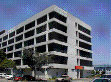
Concrete shear-wall buildings (Table 3.1 C2) are usually cast in place, and show typical signs of cast-in-place concrete. Shear-wall thickness ranges from 6 to 10 inches. These buildings generally perform better than concrete frame buildings. They are heavier than steel-frame buildings but more rigid due to the shear walls. Damage commonly observed in taller buildings is caused by vertical discontinuities, pounding, and irregular configuration.
 |
|
|
True |
|
|
False |
| 9. |
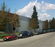
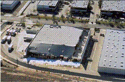
In Tilt-up buildings ( Table 3.1 ) PC1. Tilt-ups are typically one or two stories high and are basically rectangular in plan.
- Exterior walls were traditionally formed and cast on the ground adjacent to their final position, and then “tilted-up” and attached to the floor slab.
- The roof can be a plywood diaphragm carried on wood purlins and glulam beams or a light steel deck and joist system, supported in the interior of the building on steel pipe columns.
- Weak diaphragm-to-wall anchorage results in the wall panels falling and the collapse of the supported diaphragm (or roof).
  |
|
|
True |
|
|
False |
| 10. |
URM, un-reinforced masonry buildings, ( table 3.1 URM). These buildings often used weak lime mortar to bond the masonry units together.
- Arches are often an architectural characteristic of older brick bearing wall buildings.
- Other methods of spanning are also used, including steel and stone lintels. Un-reinforced masonry usually shows header bricks in the wall surface. The performance of this type of construction is poor due to lack of anchorage of walls to floors and roof, soft mortar, and narrow piers between window openings.
 |
|
|
True |
|
|
False |
|