| 1. |
The shape of highway tunnels are usually: |
|
|
Circular |
|
|
Rectangular |
|
|
Horse shoe |
|
|
All of the above |
| 2. |
Road tunnels should have ______________as that of surface roads |
|
|
At least the same traffic capacity |
|
|
More traffic capacity |
|
|
Less traffic capacity |
| 3. |
Geotechnical investigations are critical for proper planning of a tunnel. Selection of the alignment, cross section, and construction methods is influenced by the geological and geotechnical conditions, as well as the site constraints. Good knowledge of the expected geological conditions is essential. The type of the ground encountered along the alignment would affect |
|
|
the selection of the tunnel type |
|
|
its method of construction |
|
|
both above |
| 4. |
Which one of the process below is performed in the design of a road tunnel. |
|
|
Define the functional requirements, including design life and durability requirements; |
|
|
Carry out the necessary investigations and analyses of the geologic, geotechnical and geohydrological data |
|
|
Conduct environmental, cultural, and institutional studies to assess how they impact the design and construction of the tunnel; |
|
|
Perform tunnel type studies to determine the most appropriate method of tunneling. |
|
|
Establish design criteria and perform the design of the various tunnel elements. Appropriate initial and final ground support and lining systems are critical for the tunnel design, considering both ground conditions and the proposed method of construction. Perform the design in Preliminary and Final design phases. Interim reviews should be made if indicated by ongoing design issues. |
|
|
Establish tunnel alignment, profile and cross-section |
|
|
Determine potential modes of failure, including construction events, unsatisfactory long-term performance, and failure to meet environmental requirements. Obtain any necessary data and analyze these modes of failure; |
|
|
Perform risk analysis and identify mitigation measures and implement those measures in the design |
|
|
Prepare project documents including construction plans, specifications, schedules, estimates, and geotechnical baseline report (GBR). |
|
|
All of the Above |
| 5. |
The tunnel cross section geometrical configuration must satisfy the required traffic lanes, shoulders or safety walks, suitable spaces for ventilation, lights, traffic control system, fire/life safety systems, etc. The cross section is also dictated by the method of tunnel construction. For example, bored tunnels using TBM will result in circular configuration, while cut and cover construction will result in rectangular configuration. The structural systems will also vary accordingly. The available spaces in a circular cross section can be used to house tunnel systems, such as the ventilation duct or fans, lighting, traffic control systems and signs, close circuit TV, and the like. For rectangular sections the various systems can be placed overhead, invert or adjacent to the traffic lanes if overhead space is limited. It is essential at early design stages to pay attention to detail in laying out the tunnel cross-section to permit easy inspection and maintenance not only of mechanical and electrical equipment, but also of the tunnel structure itself. |
|
|
True |
|
|
False |
| 6. |
In a typical tunnel which one the following cross section elements (Figure 2-4, page 62) includes |
|
|
Travel lanes |
|
|
Shoulders |
|
|
Sidewalks/Curbs |
|
|
Tunnel drainage |
|
|
Tunnel ventilation |
|
|
Tunnel lighting |
|
|
Tunnel utilities and power |
|
|
Water supply pipes for firefighting |
|
|
Cabinets for hose reels and fire extinguishers |
|
|
Signals and signs above roadway lanes |
|
|
CCTV surveillance cameras |
|
|
Emergency telephones |
|
|
Communication antennae/equipment |
|
|
Monitoring equipment of noxious emissions and visibility |
|
|
Emergency egress illuminated signs at low level (so that they are visible in case of a fire or smoke condition) |
|
|
All of the above |
| 7. |
What are the ventilation systems option for tunnels? |
|
|
Longitudinal ventilation |
|
|
Transverse ventilation |
|
|
Longitudinal and transverse ventilation |
| 8. |
High light levels (Portal light zone) are usually required at the beginning of the tunnel during the daytime to compensate for the "Black Hole Effect" that occurs by the tunnel structure shadowing the roadway as shown on Figure 2-7. However, these highlight levels will be used only |
|
|
At night time |
|
|
During daytime |
| 9. |
In determining portal locations and where to end the approach structure and retaining walls, protection should be provided against flooding resulting from high water levels near bodies of water and tributary watercourses, or from storm runoff. Figure 2-8, page 68. The height of the portal end wall and the approach retaining walls should be set to a level at least ______ higher than the design flood level. |
|
|
2 ft higher |
|
|
4 ft higher |
|
|
6 ft higher |
| 10. |
In order to plan and design a road tunnel which one of the following components may be included in the program? |
|
|
Existing Information Collection and Study |
|
|
Surveys and Site Reconnaissance |
|
|
Geologic Mapping |
|
|
Subsurface Investigations |
|
|
Environmental Studies |
|
|
Seismicity |
|
|
Geospatial Data Management |
|
|
All of the above. |
| 11. |
Vertical and slightly inclined test borings (Figure 3-5) and soil/rock sampling are key elements of any subsurface investigations for underground projects. The location, depth, sample types and sampling intervals for each test boring must be selected to match specific project requirements, topographic setting and anticipated geological conditions |
|
|
True |
|
|
False |
| 12. |
Sampling-overburden soil; Standard split spoon (disturbed) soil samples (ASTM D-1586) are typically obtained at intervals not greater than _________ and at changes in strata. Continuous sampling from one diameter above the tunnel crown to one diameter below the tunnel invert is advised to better define the stratification and materials within this zone if within soil or intermediate geomaterial. |
|
|
5 feet |
|
|
10 feet |
|
|
15 feet |
| 13. |
The primary purpose of the GBR ( geotechnical Baseline Report) are:
- Establish a contractual document that defines the specific subsurface conditions to be considered by contractors as baseline conditions in preparing their bids,
- Establish a contractual procedure for cost adjustments when ground conditions exposed during construction are poorer than the baseline conditions defined in the contract documents.
|
|
|
True |
|
|
False |
| 14. |
Figure 5-3 is an example of |
|
|
Bored or mind tunnel |
|
|
Rock tunnel |
|
|
Immersed tunnel |
|
|
Cut and Cover |
| 15. |
In figure 5-2 , in the conventional “bottom-up” construction, a trench is excavated from the surface within which the tunnel is constructed and then the trench is backfilled and the surface restored afterward. The trench can be formed using open cut (sides sloped back and unsupported), or with vertical faces using an excavation support system. In bottom-up construction, the tunnel is completed ______ it is covered up and the surface reinstated. |
|
|
Before |
|
|
After |
| 16. |
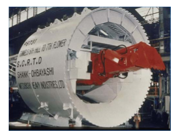
Shield tunneling, Figure 7-2 is an example of a digger shield, used in soft grounds. However, digger shield machines too often met with __________ and were usually unsatisfactory for three reasons:

- Ground loss occurred ahead and above the shield when retracting the doors or poling plates. Typically, the orange-peel doors could not be retracted in tune with the forward progress of the shield. Also when retracting the doors, the miner does not have access to deal with running ground. Thus the machine encouraged unwanted ground movement, rather than controlling it.
- Maintaining the right soil “plug” in the invert was always a headache.
- Mounting the digger in the center created a "Catch 22": if the ground movement in the center became excessive, the only way to stop it was to cram the digger bucket into the face. However, that made it impossible to excavate and move the shield forward because to do so meant the bucket had to be moved, allowing the face to fail
|
|
|
Poor results |
|
|
Excellent results |
| 17. |
Figure 9-19 shows |
|
|
construction of the tunnel entrance |
|
|
Shotcrete canopy construction after completion of portal collar and pre-support. |
| 18. |
In figure 9-20, Tunnel excavation causes a disturbance of the initial state of stress in the ground and creates a three dimensional stress regime in the form of |
|
|
a bulb around the advancing tunnel face. |
|
|
A hoop strength around the tunnel shaft. |
| 19. |
Figure 10-1, Cast-in-place concrete linings are generally installed sometime after the initial ground support. Cast-in place concrete linings are used in both soft ground and hard rock tunnels and can be constructed of either reinforced or plain concrete. Cast-in-place concrete linings can take on _____________, with the shape being determined by the use, mining method and ground conditions. |
|
|
Any geometric shape |
|
|
Only square shape concrete |
| 20. |
Figure 10-2, Steel plate linings (liner plates) are a type of segmental construction where steel plates are fabricated into arcs that typically are assembled inside the shield of a tunnel boring machine to form a ring. The steel plate lining may form the initial and final ground support. The segments are provided with gaskets to limit the inflow of ground water into the tunnel. Steel plates are also used in lieu of lagging where steel ribs are used as the initial ground support. With the advent of precast concrete segments, liner plates are not used as much as previously. |
|
|
True |
|
|
False |
| 21. |
Structural design will be governed by the |
|
|
latest AASHTO LRFD Bridge Design Specifications. |
|
|
The AASHTO |
| 22. |
Which one of the following disadvantages a cast in place lining would have? |
|
|
Concrete placement, especially around reinforcement can be difficult. The nature of the construction of the lining restricts the ability to vibrate the concrete. This can result in incomplete consolidation of the concrete around the reinforcing steel. |
|
|
Reinforcement when used is subject to corrosion and resulting deterioration of the concrete. This is a problem common to all concrete structures, however underground structures can be also be subject to corrosive chemicals in the groundwater that could potentially accelerate the deterioration of reinforcing steel. |
|
|
Cracking that allows water infiltration can reduce the life of the lining. |
|
|
Chemical attack in certain soils can reduce lining life. |
|
|
Construction requires a second operation after excavation to complete the lining. |
|
|
All of the above. |
| 23. |
Figures 10-7 and 10-8, show: |
|
|
Precast segments for One-Pass Lining for a tunnel |
|
|
Concrete dividers for the side and middle of the road |
| 24. |
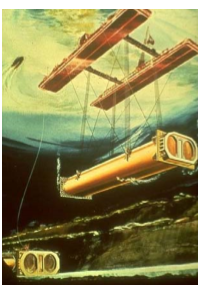
Immersed tunnels consist of very large pre-cast concrete or concrete-filled steel tunnel elements fabricated in the dry and installed under water. More than a hundred immersed tunnels have been built to provide road or rail connections. They are fabricated in convenient lengths on shipways, in dry docks, or in improvised floodable basins, sealed with bulkheads at each end, and then floated out. Tunnel elements can and have been towed successfully over great distances. They may require outfitting at a pier close to their final destination. They are then towed to their final location, immersed, lowered into a prepared trench, and joined to previously placed tunnel elements. After additional foundation works have been completed, the trench around the immersed tunnel is backfilled and the water bed reinstated. The top of the tunnel should preferably be at least 5 ft (1.5 m) below the original bottom to allow for sufficient protective backfill. However, in a few cases where the hydraulic regime allowed, the tunnel has been placed higher than the original water bed within an underwater protective embankment.

|
|
|
True |
|
|
False |
| 25. |
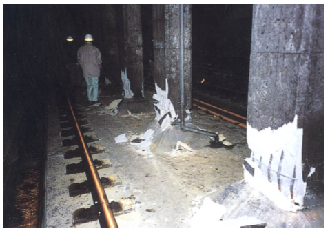
Reporting on the seismic performance of shallow cut-and-cover box-like tunnels has been relatively poor in comparison to the performance of bored/mined tunnels. This was especially evident during the 1995 Kobe, Japan, earthquake (O’Rourke and Shiba, 1997; Power et al., 1998). Figure 13-10 and Figure 13-11 show the damage to the center columns of the cut-and-cover tunnels running between Daikai and Nagata Stations during the 1995 Kobe Earthquake.

|
|
|
True |
|
|
False |
|